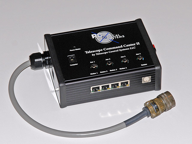
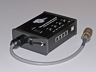
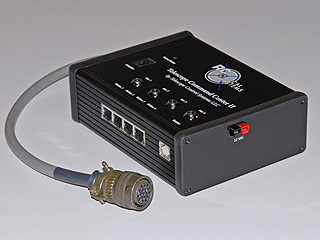
Telescope Command Center - TCC-II...
Telescope Command Center...
Made exclusively for RCOS by Telescope Control Systems, LLC.
(Discontinued as of 2010)
The TCC-II was released fall of 2007 and is the predecessor to the original TCC-I which was developed in 2001. In addition to the features listed below for the original TCC-I, the TCC-II has:
- Added 4 additional stepper motor drivers.
- Increased torque on PIR stepper drive to rotate even the new heavy off axis filter wheels.
TCC Software / Firmware and Help Files
The Telescope Command Center is a combination of hardware and software designed to control the peripheral functions of the RC Optical Systems line of telescopes. The TCC hardware consists of a processing unit attached to the telescope and a hand held display unit used for user control. The TCC can also be simultaneously controlled via computer through its serial port.
The TCC-II provides control for the following functions of RC Optical Systems
telescopes:
- Precision focusing of the secondary mirror via a servo controlled linear actuator designed by RCOS in 1999. Resolution is 1/40,000 of an inch.
- Instrument rotation by use of an RCOS Precision Instrument Rotator (PIR).
- Temperature monitoring of the primary and secondary mirrors and ambient temperature moving through the telescope with manual or automatic control of the cooling fans and or dew heater(s).
- Precise control of secondary mirror dew heater manually or automatically.
- Four zones of variable power 60 watt DC auxiliary outputs which can be used to control other variable power 12VDC devices.
- High torque stepper motor driver specific to the RCOS PIR.
- Four additional stepper motor (motion) outlets.
Almost all of the Telescope Command Centers capabilities are available via
the scripting interface. This interface is ASCOM compliant, and uses platform-independent
COM (ActiveX) interfaces for compatibility with the built-in Windows scripting
host and many programming languages. The TCC seamlessly integrates with ASCOM
compliant programs such as MaxIm DL CCD and FocusMax.
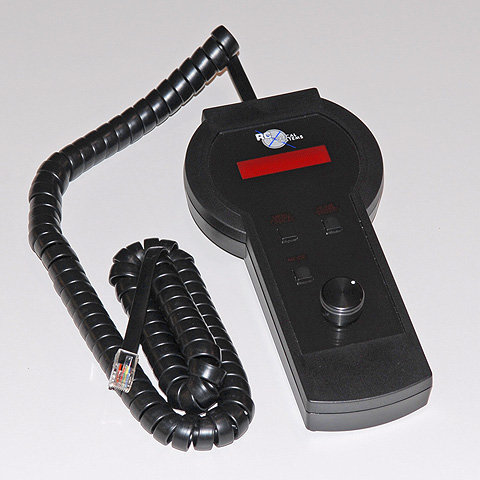
The Hand controller can be used to duplicate all functions performed by a PC.
The TCC software allows for computer control of the TCC hardware. The TCC can simultaneously be controlled via the hardware interface and any number of ASCOM compliant computer links. The status of all TCC functions remain synchronized across all connected user interfaces. Conversely, the TCC hardware is fully operational via the TCC software or ASCOM link, without the use of the hand controller.
The TCC software extends the functionality of the TCC by adding:
- Adjustment of servo parameters of Secondary Dew Heater and Fan control.
- Fine tuning of the Focus servo filter parameters.
- Logging of Temperatures, Secondary Dew Heater and Fan powers, allowing for fine tuning of these automatic control functions.
The TCC software is fully ASCOM compliant and registers itself as an ASCOM
compliant Focuser during installation, and is thus visible to all ASCOM compliant
software packages such as MaxIm DL CCD. There are two program window sizes
options available. The large window option allows for full control of all
the TCC options. There is also a miniature stay-on-top window which allows
for control of all the TCC core functions, while utilizing a small amount
of computer screen real estate. The miniature window option is particularly
useful when used in conjunction with a secondary ASCOM compliant program such
as MaxIm DL CCD or FocusMax.
Closed Loop Servo DC Secondary Focuser...
Your RC Optical Systems telescope contains a precision secondary mirror actuator with an integrated servo motor and position encoder. This system allows for a position resolution of 1/40,000 inch which is approximately 40 times the focus tolerance of your optical system.
In order to fully utilize the TCC focus capabilities it is helpful to understand to workings of the focus servo motor. When a command is issued to change the focus position, the motor is moved in the desired direction. The TCC reads the position of the secondary mirror 6000 times every second and determines the magnitude and sign of the difference between the desired position and the actual position. This difference is referred to as the Error Term and is used by the servo algorithm to determine how much power to supply to the motor. The power output is directly proportional to the Error Term (the Proportional Term) and inversely proportional to the rate of change of the Error Term (the Derivative Term). In addition, any residual Error Term accumulates over time (the Integral Term) and directly contributes to the power output. The Proportional Term contributes to the reactivity of the system, the Derivative Term adds stability to the system, and the Integral Term increased overall position accuracy.
The various servo algorithm terms have been optimized for a typical RC Optical Systems secondary focuser. However, because every system is unique it may be possible for the user to further tune the servo system.
The TCC main application Focus Tab displays both the Target position and the Actual position of the focuser. The knowledge of both positions is helpful for determining when the focus has settled and if there is any error in positioning. The TCC servo parameters are set to provide a balance of stability and position accuracy. It is not unusual for the system to settle with a difference of up to 2 counts between the actual position and the desired position. This residual error is immaterial because it is well within the focus tolerance of the optical system.
When the TCC is powered up, the focuser position readings are set to zero.
Movement of the focuser results in a position reading that indicates a position
relative to this starting position. To obtain position readings that indicate
the absolute position of the mirror, the TCC must first be commanded to move
to the Home position. The Home position is a precision mechanical stop within
the focus actuator and allows for reliable repeatability of absolute positioning.
Once the TCC detects the Home position the focuser is moved 1/2,000 inch to
relieve any mechanical tension. Thus the Home position corresponds to a position
reading of 20 counts.
Auto Focus Routine...
The TCC works very well with the "auto focus" routine from FocusMax and MaxIm DL.
Temperature Control...
Use the Temperature tab to control the many temperature-related functions of the TCC. These include telescope cooling via fan control, secondary mirror dew heating, and auxiliary variable power outputs which can be used to control dew heater elements. The TCC monitors three pertinent temperature: ambient, primary mirror, and secondary mirror; which are displayed in degrees Fahrenheit. These temperatures can be used to guide telescope cooling and secondary mirror heating, and are used for automatic control of these functions.
The two modes of cooling fan control are manual mode and automatic mode. In manual mode, the fan speed (power) is adjusted by pressing the Power (%) up/down arrows. In automatic mode, the fan speed is automatically adjusted in response to the relative Primary Mirror and Ambient temperatures according the equation:
Power (%)=(Primary T -(Ambient T+ Set Point T))/Servo Gain x 100%
Where Set Point defines an offset to Ambient T and Servo Gain defines a temperature range over which the Power will vary from 0-100%. For example: With an Ambient T of 60 ºF, a Set Point of 1 ºF, and a Servo Gain of 2 ºF, the Power will equal 0% when the Primary T is less than 61 ºF, 50% when the Primary T equals 62 ºF, and is 100% when the Primary T is greater than 63 ºF.
Note: To insure that cooling fans operate over their full speed range, see adjust fan settings.
The two modes of secondary mirror heater control are manual mode and automatic mode. In manual mode, the heater power is adjusted by pressing the Power (%) up/down arrows. In automatic mode, the heater power is automatically adjusted in response to the relative Secondary Mirror and Ambient temperatures according the equation:
Power (%)=((Ambient T+ Set Point T)-Secondary T)/Servo Gain x 100%
Where Set Point defines an offset to Ambient T and Servo Gain defines a temperature range over which the Power will vary from 0-100%. For example: With an Ambient T of 45 ºF, a Set Point of 0.5 ºF, and a Servo Gain of 3 ºF, the Power will equal 0% when the Secondary T is greater than 45.5 ºF, 50% when the Secondary T equals 44 ºF, and is 100% when the Secondary T is less than 42.5 ºF.
The two auxiliary power outputs are adjusted through their respective slider
bars. Each output is capable of supplying 60 watts of power and can be used
to control any device which requires a variable power (pulse width modulated)
DC power, such as resistive heating elements like those supplied by Kendrick.
Precision Instrument Rotator...
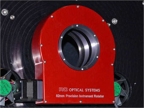
Shown above is the RCOS 82mm Precision Instrument Rotator (PIR-82mm).
The RCOS instrument rotator in controlled through the Instrument Rotator tab. The instrument rotator drive consists of a precision worm drive powered by a high quality stepper motor, which provides a resolution of 1/200 degree of rotation.
To command the instrument rotator to move, set a rotation step size by clicking an available option, or by choosing Other and typing step size. Press the Up arrow to rotate clockwise and the Down arrow to rotate counter-clockwise. Keeping the buttons depressed will cause the movement command to be continually repeated. The instantaneous rotator position is displayed and updated during rotation.
Pressing the Home button will cause the instrument rotator to rotate counter-clockwise to one of its two home position. The rotator slews at a rate of approximately 3.25 degrees/sec. It takes 110 seconds to complete a full rotation. To reduce the amount of time it takes slew home, the instrument rotator contains two positions sensors place 180 degrees apart. Therefore, position reading after a home maneuver may read either 0 or 180 degrees, depending on which home position is detected first.
Pressing the Stop button will halt a rotator slew at its current position.
And since this is now a PC based control system, we expect new and improved features will be available as a software download.
Software and drivers can be user installed directly to the control board.
| Telescope Command Center (TCC): |
|